DATA LOGGER ROCKET V2
Though I gathered some great data from the first flight of my Data Logger Rocket, I was unsatisfied with its flight performance and wanted to build a more refined and powerful of my original design. After many hours of redesign, touch-ups, and simulation, I produced a shorter, more powerful, and more stable data logger vehicle.
Larger motor
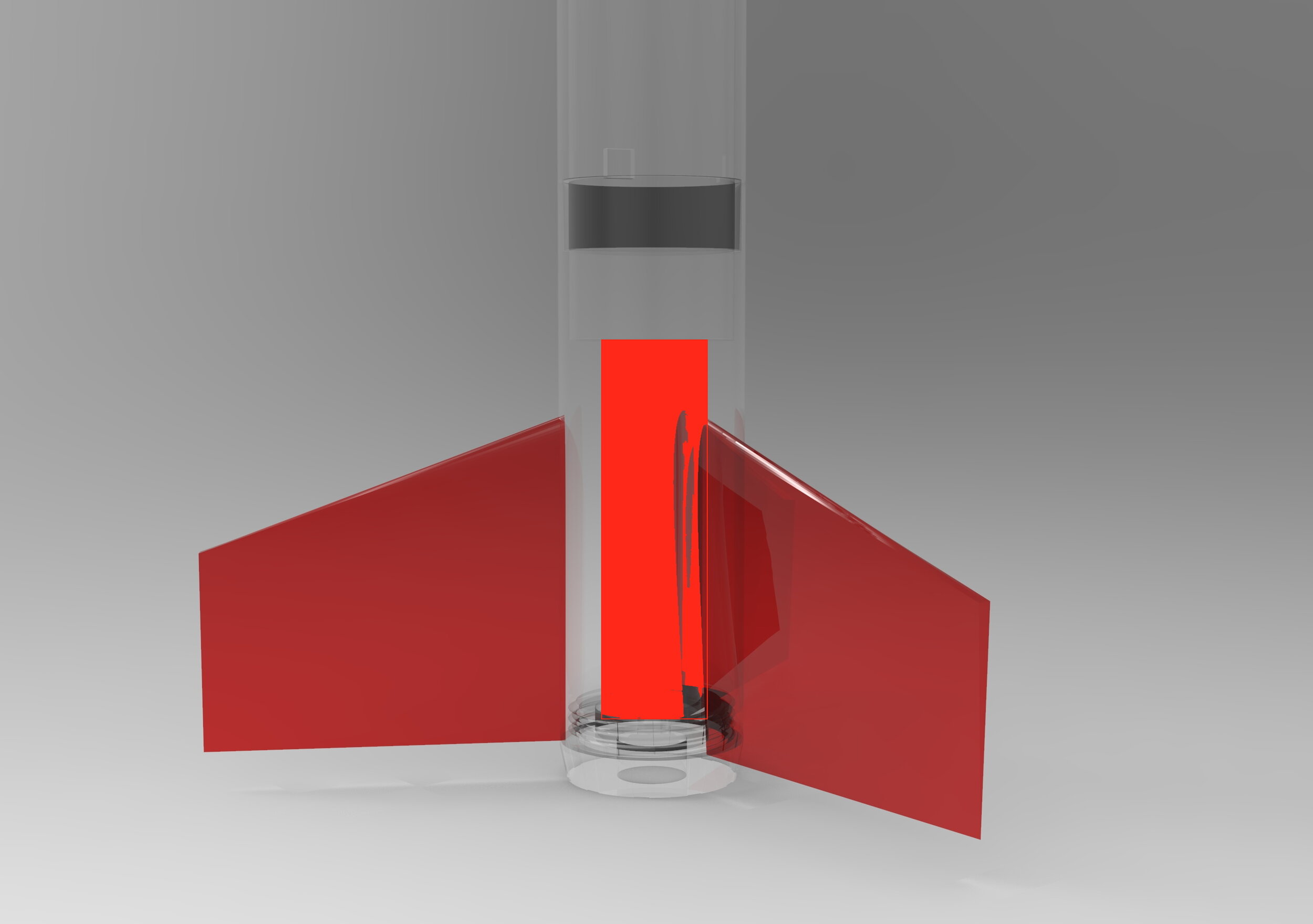
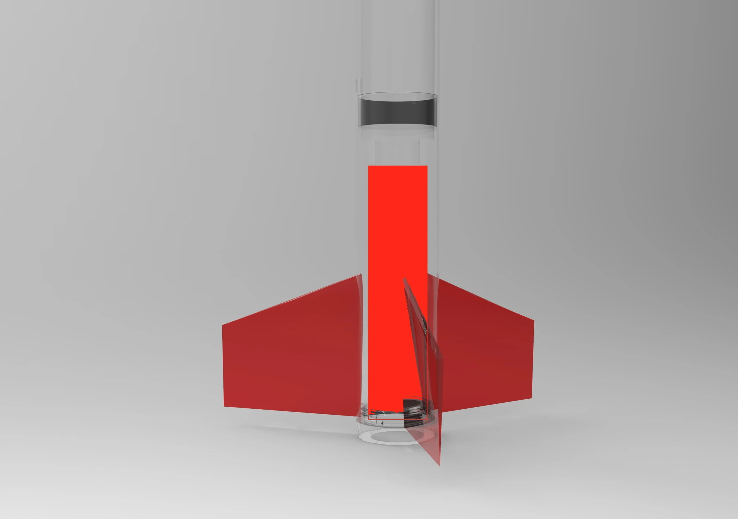
The primary issue with V1 was the weakness of its C6 motor, which was under powered for its form factor. V2 features a larger 24mm motor mount which supports an Estes E12-6 rocket motor. The E12 boasts 29.6Ns of impulse, nearly triple the C6’s 10.0Ns, pushing the vehicle’s simulated apogee to an impressive 456m (1496ft). Additionally, the greater velocity of V2 off the launch rod provided by its larger motor increases its flight stability. The original and revised motor mounts can be seen below hatched in red.
V1
V2
V1 Battery Placement
Relocated Center of mass (COM)
Another main issue with V1 was its over stability, or the placement of its COM significantly ahead of of its center of pressure (CP). An over stable rocket tends to lean into the wind very easily and will often a more parabolic path than a ‘less’ stable rocket, as evidenced from V1’s first flight.
To correct the over stability in V2, I moved the 9V battery from the nose cone (hatched in blue, left) to just below the avoinics bay. As the battery had originally been stored in the nose cone for ease of access before launch, I added a longer connector to the battery allowing it to be connected after final assembly. This also increased the height of the rocket, but reduced its stability from 3.2 Cal to 2.0 Cal! Ideally, a model rocket will have a stability of ~1 Cal, however due to the payload requirement of this model, I felt 2 Cal was acceptable. The battery now mounts just below the 9DOF gyro/accelerometer/barometer into a friction-fit 3D printed sleeve (hatched in blue, right).
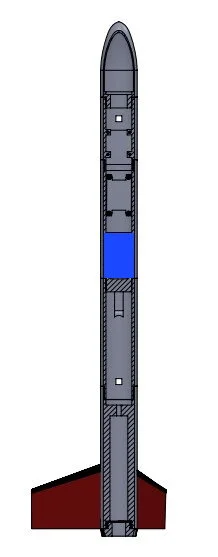
V2 Battery Placement
Modeling and Simulation
Like V1, I modeled and simulated this vehicle in OpenRocket (OR) during my design process. I used SolidWorks material specification and the mass properties tool, combined with electronic component datasheets to manually configure the rocket’s mass distribution in OR, resulting in a fairly accurate model. According to OR, V2 has an apogee of nearly 1500ft with a max velocity of mach 0.32 (109m/s)- very respectable for a model vehicle carrying such a payload!
V2 Modeled in OR
Plot of OR Simulation Results
Vehicle Assembly
V2 is composed of 13 parts that must be assembled very carefully in order to ensure optimal performance and enable consistent data recovery. One major challenge in designing this rocket was making the electronics assembly secure, easy to install, and easy to debug. The rocket features two status LEDS, and electronic components are secured using four M2 screws via thru-holes in the avionics bay. Extra space around the components allows for wires, connectors, and the installation of the arduino nano board that drives the data recorder.
Parts Required for V2 Assembly
Installation of the SD Card Reader Board
Installation of the 9DOF Gyro/Accelerometer/Barometer Board
Launch Logistics and Flight
I used the same remote-controlled launch pad that I used for V1 to launch this rocket. I set it up angled slightly ‘downrange’, as I was launching from one end of a nearby park. After conducting safety checks on the launch circuit and pre-flight checks on the rocket, I started the countdown before sheltering behind a fence.
As expected, V2 flew very, very high. In fact, it flew much farther downrange than expected. I found the bottom stage (with a broken shock cord) about 1000ft downrange, though was never able to recover the top of the vehicle containing the electronics and data. That being said, the primary goal of this vehicle was to improve V1’s flight performance, which this definitely accomplished!