3D Printed Data Logger Rocket
Before getting serious about testing the thrust-vectored model rocket that I’m woking on, I wanted to launch a smaller, simpler rocket for a few reasons. First, I wanted to verify that I could log reliable flight data and import it into Microsoft Excel for later review. I also wanted to make sure that my flight computer could detect a rocket’s launch, cruising period, and apogee. Finally, I wanted to test my launchpad and groundstation before using them to launch a much more complicated rocket.
The Rocket
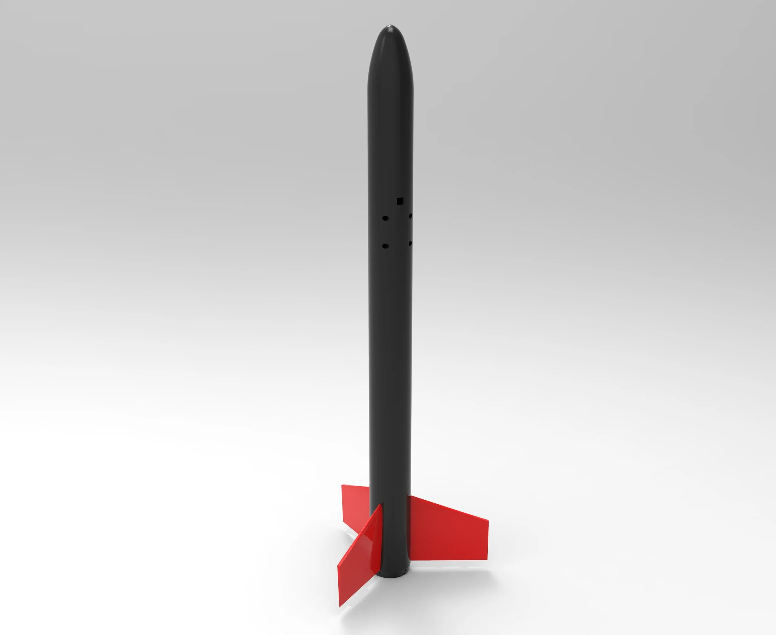
The data logger rocket consists of six 3D printed parts and is powered by an 18mm Estes rocket motor (I’m using a C6. Standing at 43cm with an outer diameter of just 32mm, it’s fairly small, but is still able to carry a parachute, three sensors, an arduino, an SD logger board, and a 9-volt battery.
Modeling and Simulation
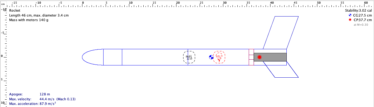
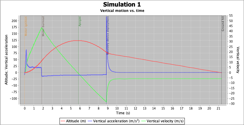
In order to test the stability of my design, I modeled the rocket in the free model rocket simulation software OpenRocket (OR). Using Solidworks to calculate the masses of each of my 3D printed components, I added the masses of the electronics that would be contained in each segment and used OR’s mass override feature to accurately model the rocket’s distribution of mass. I was also able to accurately model the dimensions of the rocket’s fins using the “freeform” fins option. I ended up with this design (left), which is pretty stable. Additionally, I was able to generate a simulated vertical motion vs time plot for my rocket (right), which places its apogee around 100m. This is fine seeing as the C6 I’m using is pretty underpowered for this size vehicle.
Avionics and Data Logging
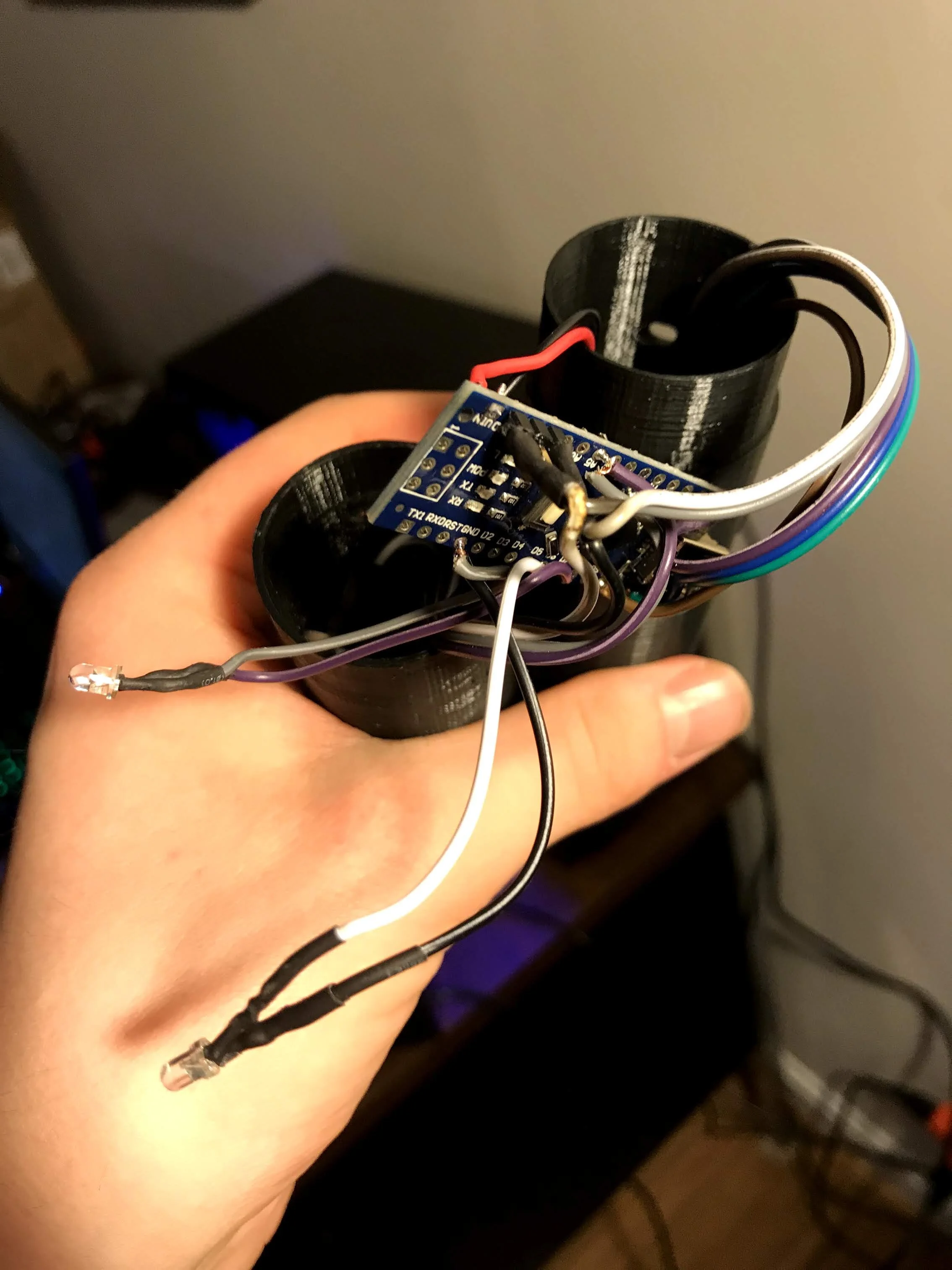
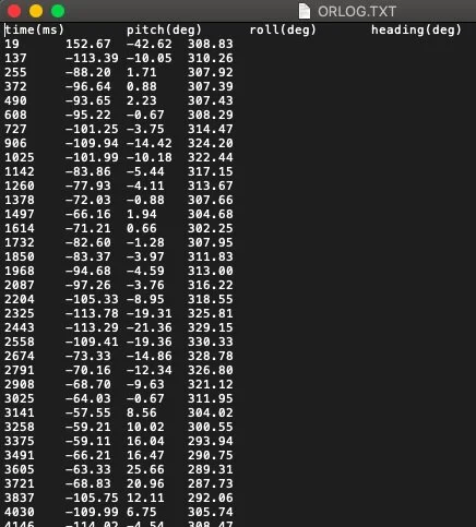
The rocket’s flight computer is comprised of an Arduino nano, Adafruit 10DOF sensor, Adafruit SD card breakout board, and two status indicator LEDs. The sensors are mounted inside the fuselage segments using M2 screws and the whole thing is powered by a single 9-volt battery. The computer logs the rocket’s pitch, roll, heading, altitude, and acceleration in the x, y, and z directions vs time to three respective files at a rate of just over 8.5HZ.
Sample Data
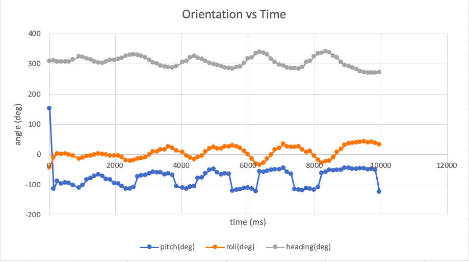
Log files (left) can be imported into excel and plotted in a chart. Example data is displayed below. Being able to record flight data and study it later will be critical to the development of more complicated rockets.
Parachute attached to the rocket fuselage
Recovery System
My rocket needed a recovery system so I installed an Estes parachute and recovery wadding paper. The rocket splits very low down (just below its first launch lug) because it’s carrying electronics above. Model rockets generally eject their parachutes by popping off the nose cone.
Rocket sitting on the launch pad. I forgot a 9v battery so I used a LiPo from one of my drones
Launch Logistics
In order to launch this rocket, I needed a launch pad, so I cut a piece of plywood down to an appropriate size and purchased a 1/8” steel rod. 3D printing a brace for the rod, a pad to place the rocket upon, and shields to protect the electronics from soot spewn out of the rocket, I assembled everything using 1/4” wood screws. The launch rod can be pushed through the bottom of the launch pad into the ground for extra stability.
Once I’d completed the structure, I wired up an arduino uno, relay, and xBee radio on a solderless breadboard. I then added a piezo buzzer and three status LEDs. Using the xBee to receive instructions from my laptop, the launch pad has four states:
State 1: WaitingThe launch pad sends an ‘initialized’ signal to my laptop and waits for the ‘launch’ signal
State 2: StandbyThe launch pad starts the launch sequence by sending a message to my laptop and blinking the blue LED for five seconds, giving me time to abort if I didn’t mean to launch the rocket
State 3: CountdownAfter waiting five seconds, the red LED begins blinking and the buzzer counts down from ten. The launchpad also sends the countdown over to my laptop.
Stage 4: Motor IgnitionThe green LED turns on and the relay closes, shorting the 9v battery and launching the rocket!
Close-up video of the rocket launch
Video of the rocket’s flight
Results
The rocket didn’t fly quite as I was hoping for for two reasons. First, the rocket is over stable and tends to lean into the wind. This only get worse as the motor burns up as you can see in the video. This issue is exacerbated by the fact that the C6 motor powering the rocket is under powered seeing as the rocket is powering cargo. This means that the rocket is not moving fast enough to be as aerodynamically stable as it could be when it leaves the launch pad. Finally, my parachute mechanism worked perfectly….. only after the rocket had already ‘landed’. This was just because I bought the wrong motors - C6-7s - that had a ejection delay of a whopping seven seconds. This, combined with the low flight due to over stability and an under powered motor, contributed to its very parabolic flight path.
Though the flight was not perfect, the mission was a success! I was able to recover 5.6 seconds of useful data from the rocket. Additionally, by syncing my video up to the graphs I produced, I could identify different stages of its flight and understand why the acceleration/orientation/height curves look like they do.