Autonomous Drone Landing Pad
A landing pad with a visual marker that enables drones to autonomously land and recharge
Concept
One of the main barriers to using UAVs (drones) commercially is their battery life. Most commercially available drones for professionals have flight times of just 15-30 minutes (1). Additionally, in applications where a drone would be carrying extra weight, such as delivering packages, this flight time will be greatly reduced. I attempted to come up with a solution to this problem: a ground station that a drone could land on autonomously mid-mission and rapidly recharge.
First, I came up with a few requirements for the landing pad and the drone’s navigation system:
Landing Pad:Easy to manufacture - I wanted my design to be 3D printable since I didn't know what other tools I'd have access to at collegeAble to charge the drone - The landing pad must have a charging port that the drone can plug into upon landingSimple landing marker - I wanted the landing marker design to be simple enough that it wouldn’t be very hard to detect, but sophisticated enough to provide the drone with enough data to guide itself onto the landing pad.
Drone:Flight control software must be able to run on cheap hardware - I used my raspberry pi 3 for this projectBattery charging leads must be routed to ports below the drone
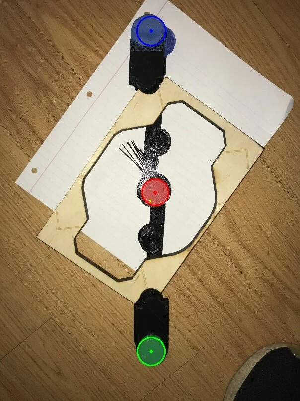
Landing Marker Rev 1
creating the landing marker
The landing marker needs to be able to provide the drone with its directional and rotational offsets from the landing pad. I decided that a simple design would just be two circles, but then realized that if the computer only detected one, it wouldn’t have enough information to land. For this reason, my first marker (rev1) had three circles: red, green, and yellow.
Rev 2
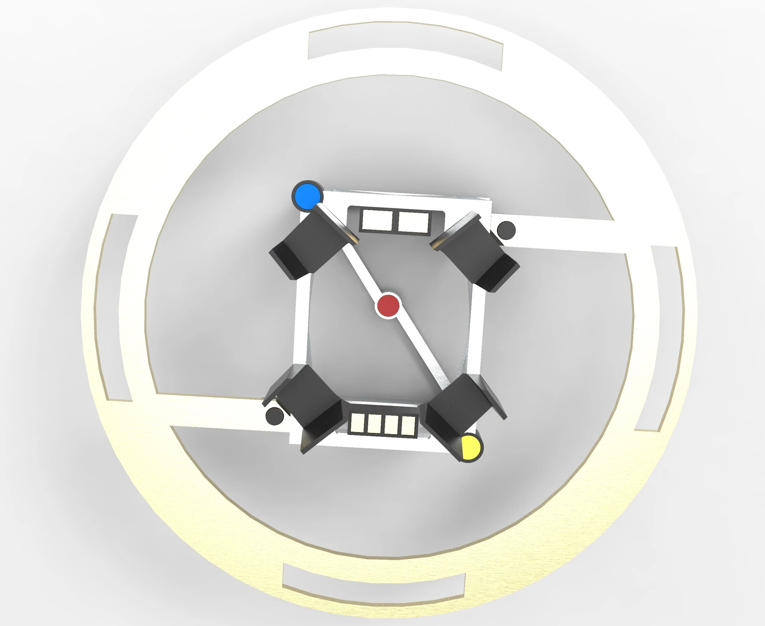
Landing Marker Rev 2
The only fault with this design was that if the circles were spread out enough for the drone to accurately find a line between them, the drone wouldn’t be able to see the outer two circles once it got below a certain altitude. To fix this, I simply added two inner circles and changed yellow to green since it was easier to work with in openCV.
Developing the Landing Marker Detector
As someone who had never touched openCV before, I knew that writing the code for this project was going to be pretty challenging. I began with simply learning how to use openCV’s Hough circle detection method (2) to detect circles of different colors and sizes. After endless hours of reading the openCV docs, coding, and testing my detector against rendered images, I developed two programs: the class HCD (for ‘Hough Circle Detector’) and calculateDetectorParams.
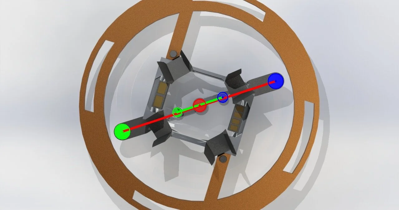
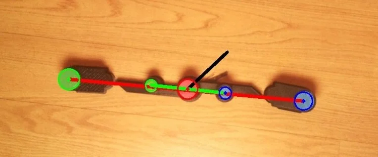
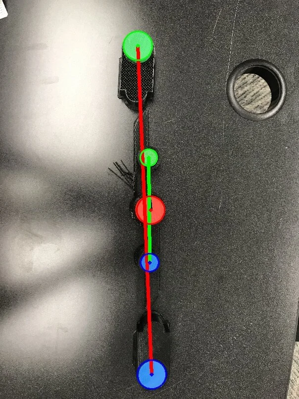
An image outputted by HCD with guide circles and lines drawn
HCD’s main method, detect, takes a camera frame and three floats as parameters and returns the offset of the drone from the center of the landing pad in polar coordinates as well as the drone’s rotational displacement from its proper alignment with the pad. HCD also draws the detected circles and drawn lines on an output image for debugging purposes.
Optimal detector parameter vs camera height
So why the other class? Well, openCV’s Hough circle method requires two parameters that don’t have any calculatable correlation to the input circle (at least not any that I could figure out). You can think of these parameters as the ‘sensitivity’ of the detector, as they basically determine how long an edge has to be for it to be considered part of a circle. I realized that I would have to empirically determine these parameters based on the height of the drone relative to the landing pad. To do this, I wrote a program, calculateDetectorParams (CDP) that used its own specialized version of the HCD class to determine the optimal parameters for detecting red, blue, and green circles in an image. As a proof of concept, I produced renders of the landing pad from various heights between 0 and 10m and an animation of a camera zooming out from the landing pad from 0m to 10m. Running each render through CDP, I plotted the optimal parameters in desmos and found a best-fit quadratic model. Using this model and a function relating frames of a video to seconds elapsed, was able to process each frame of the zooming animation at the optimal parameters dictated by the model. The results were better than I imagined, with the detector only struggling to find all three circles after ~9m or so. Of course, this is a “perfect” simulation, as we’re using a rendered video. You can see the results below! This program hasn't been touched in a long time and draws all of the circles as green for some reason, but it works as a proof of concept.
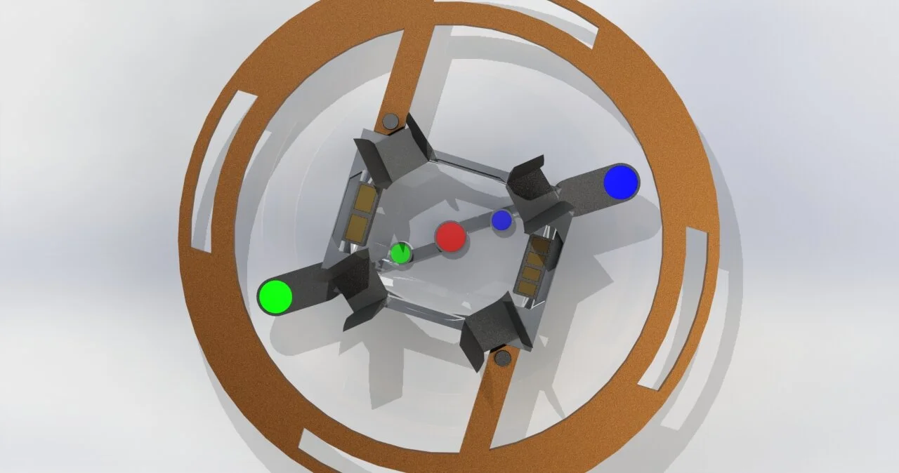
Input Render
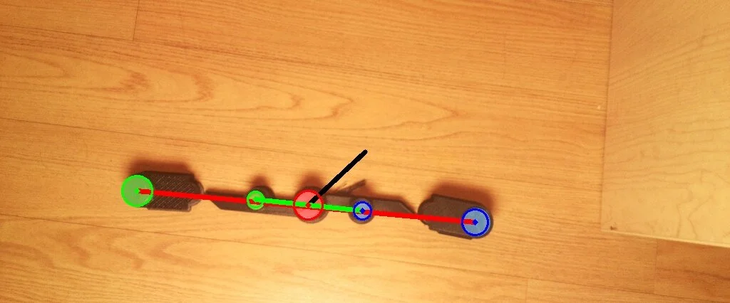
Output Video
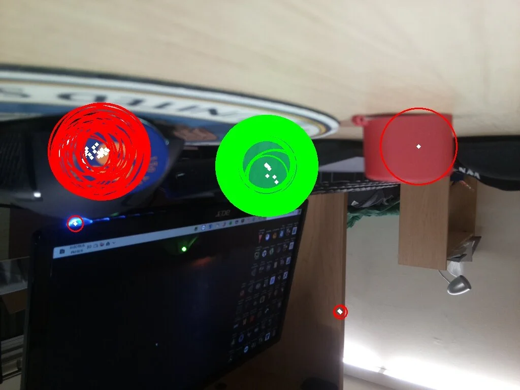
The optimal paramters for detecting this marker differ greatly from those of the red-saturated image in the paragraph above
Working with a real marker
While the above model works with the render as a proof of concept, it doesn’t work in detecting a real landing marker. I needed to generate a model using pictures of the actual marker. The only issue with this is lighting, which is where the difficulty lies in working with a visual light marker (as opposed to IR) like this one. Since the drone would have to detect the marker at all times of the day, including night, I decided to illuminate the landing pad with a bright light of a standard spectra. Since the landing pad would receive mostly ambient sunlight anyway, I ran tests using a sun lamp from my dorm to illuminate the marker. My end goal was to take pictures of the illuminated marker at different heights and run the images through CDP to generate a model like I did with the render. Before that, however, I needed to do some work on the drone and make sure that I could safely test it.
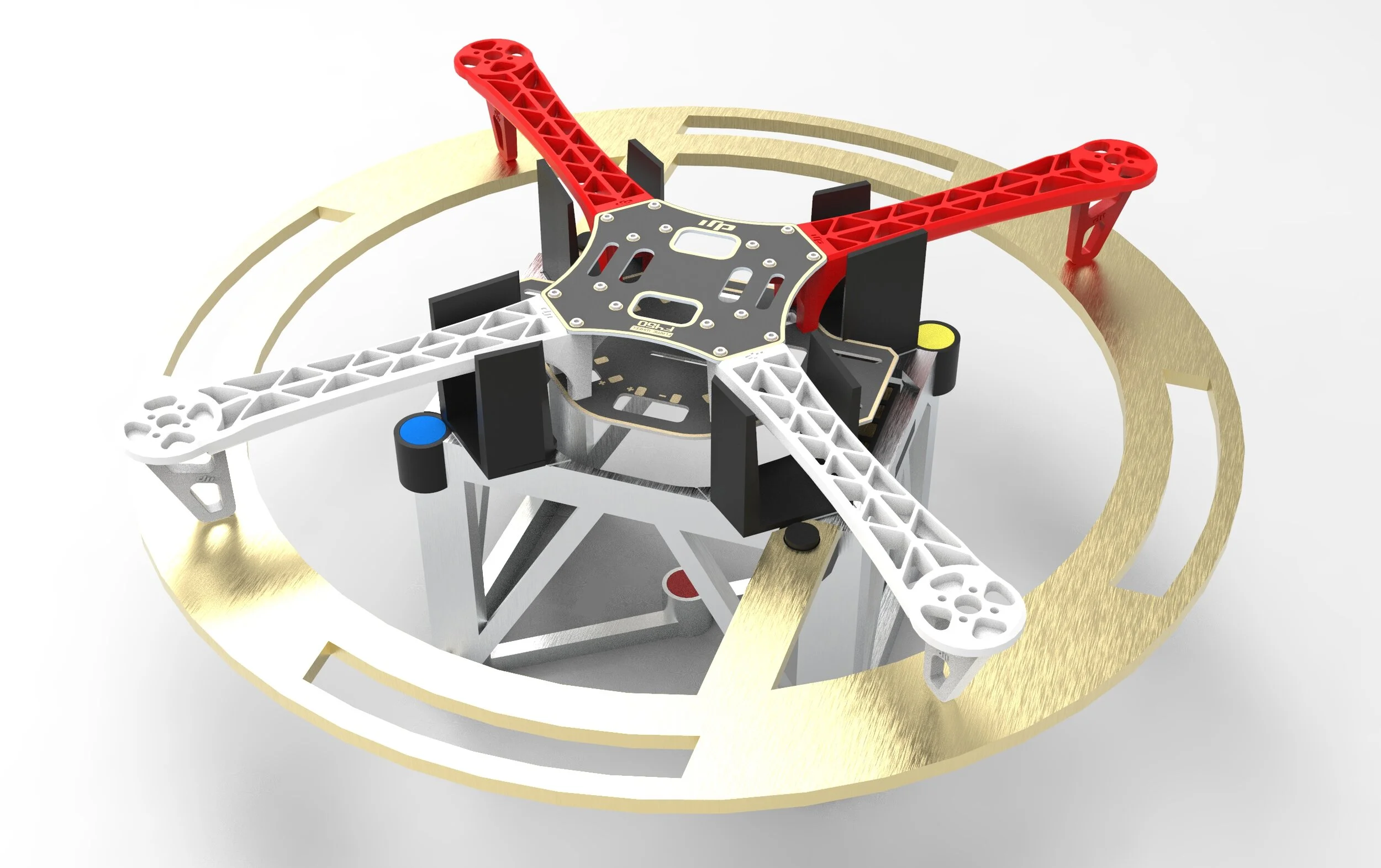
The drone
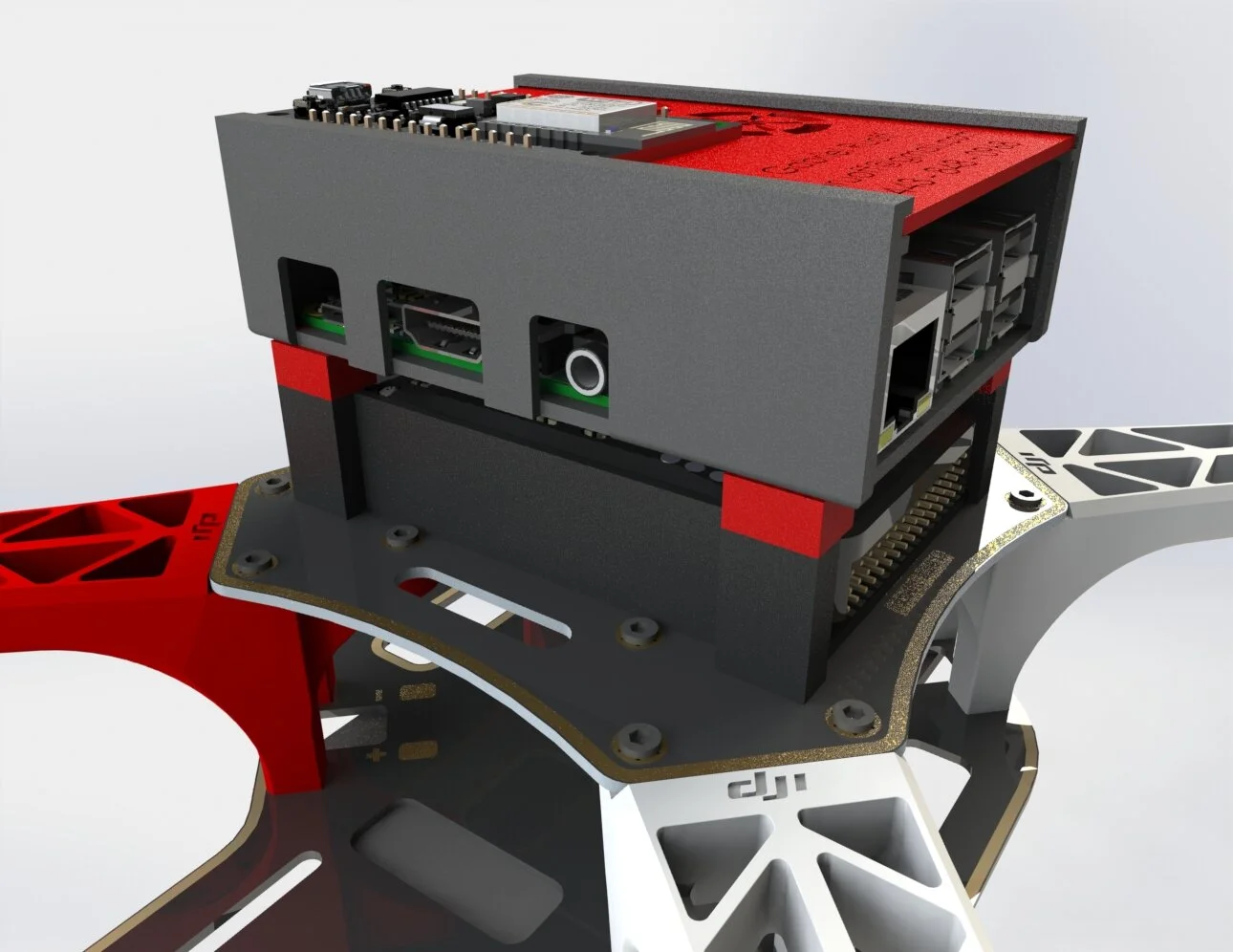
The drone is equipped with a Pixhawk 4, Raspberry Pi 3, and esp8266
For this project, I used the same drone that I used for my senior project: a custom DJI F450 equipped with a Pixhawk 4, Raspberry Pi 3, and esp8266. The code for landing the drone is fairly simple in concept, but very hard to implement and test. The pseudocode is as follows:
While the drone hasn’t landed and its landing timer (failsafe in case it cannot find the marker) hasn’t run out:Get a frame from the cameraPass the frame to HCD to get three correction factors: the drone’s offset from the landing pad in polar coordinates and its rotational offset from the landing pad in degreesFeed these correction factors into three separate PID loops to update them based on previous error informationConvert the correction factors from pixels to meters in the north and east directionsSend a way-point to the drone to correct it's position and rotation. Continue to descendIf the drone is close enough to the landing pad, break out of the loop
Once done with the loop, put drone in auto-land mode and have it land on the marker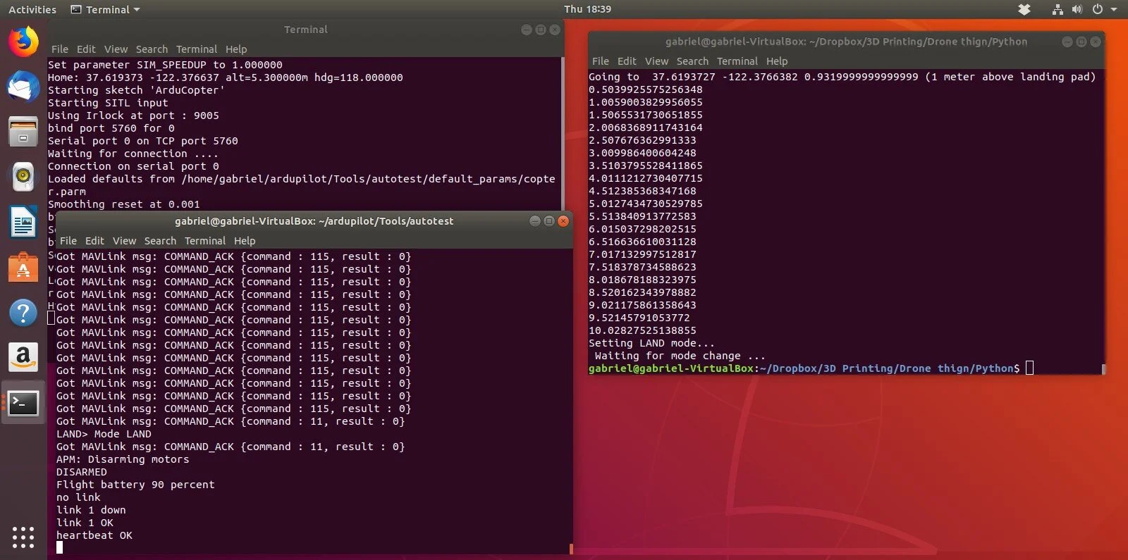
Simulating a mission with dronekit-SITL on Ubuntu 18.04.3
Testing and feasibility
Since the drone is by no means cheap or simple to repair, I needed a way to assure the basic functionality of my code while eliminating the possibility of a crash. The solution I found was dronekit-SITL, a software-in-the-loop simulator for ardupilot vehicles. Setting up a Ubuntu virtual machine, I configured everything and was able to run my code on a simulated drone running at 127.0.0.1 (localhost). Additionally, the simulator can act as a proxy - streaming data through an output address to the open-source flight simulator software FlightGear. This allowed me to see the drone’s movements in real time.
Sadly, the downfall of this project would lie in the feasibility of testing the actual drone. The nearest viable test site is a ten minute walk from my dorm building and is in a fairly populated area. Additionally, without a netted enclosure, I would not be able to stop the drone in the event of a flyaway or loss of contact. One day when I have a more suitable facility I hope to finish this project.